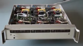
Greening the HP14570 Power Controller
This is a quite interesting piece of equipment for audio use. It takes your mains and sends it to 3 groups of 4 outputs (so total of 12). The unit basically consists of 3 group boards with all the circuitry for 4 outlets each. The outputs are filtered for differential and common mode noise and interference. Each output is separately switched on at the voltage zero crossing, and switched off at the current zero crossing. So the switching is pretty much noise free, and the filtering is ideal for powering audio stuff.
In the intended setup, the switching was done electronically through a separate piece of equipment that could be controlled through the famous IEEE interface, and which is similar to the HP-IB interface bus. You were supposed to use this thing in a lab environment to automate testing and to switch each group of test equipment on or off depending on the particular test you were doing. The external switching connections are here.
Switching is quite elegant: First a triac is used to close the output. But a triac has a little threshold voltage that would distort the nice, filtered mains sine wave. So, a short interval later, a relay bridges the triac. At switch-off, first the relay opens, then the triac. So, the relay never has to break appreciable voltage- or current levels.
 Click for full size assy drawing
I modified my 14570 so I can switch my complete audio set-up on or off either by a toggle switch on the front panel or by the IR remote I use for other functions. The set-up is such, that if I switch it on, it goes through a timed sequence and switches the equipment as follows:
- switch on my sources (CD, DVD etc) one by one;
- switch on the cross-over filters, equalizers etc one by one;
- switch on the power amps one by one.
Switching off follows a similar sequence in the other direction. The beauty of the system is that switching 'thumps' are avoided, and also that those high-inrush current power supplies of the power amps don't come on all at the same time, avoiding mains sag. And it is really nice to switch your complete system on or off by a single button press too.
The control circuit is quite simple: a 16F627 PIC microcontroller driving the switch inputs for each of the 12 channels. The software takes care of the timing and sequencing.
The circuit is supplied through the +5V DC of one of the group boards. In theory, all the grounds of the three groups are interconnected, but to avoid any possibility of ground currents, I drive the two other groups' switch inputs isolated through an opto coupler.
And ohh, yes, almost forgot. It has a receiver for a standard Philips RC5 IR remote control. Activating and deactivating my sound system now is just a lazy button press away. The IR receiver is behind a small piece of red Plexiglas behind a hole in the front panel.
The control PCB
 The control circuit only needs a small PCB that finds an easy place inside the HP14570. The +5V power comes from one of the group boards. Three flat cables link the switching outputs to each of the three Group boards.
The control signals are active low and the HP14570 control inputs have pull-ups, so to switch on an output you pull the corresponding control line low. For group A that is done directly through the PIC. As I wanted a galvanic isolation with Group B and C, I used opto couplers and pull-down transistors for those.
One issue is the connections to your switched mains outlets. The original '14570 had proprietary connectors that actually fit all 12 on the 19" back panel. Mating plugs are pure unobtanium. That means you have to use your creativity. I am currently putting together an external extension strip with a thick umbilical cable to the '14570 with switching wires for all 12 outlets. Ugly, but effective.
In parting...
If you are lucky enough to get yourself an HP14570, you want the service manual as well. You can get a .pdf version at ArtekManuals. High quality scans for a reasonable price. Tell them I send you.
